

Introduction
Modelio is a free and open-source modelling tool that enables users to create and design models in various domains such as business processes, software engineering, systems engineering, and data modelling. It provides a user-friendly interface and supports several standard modelling languages, including UML, and ERD.
Getting Started
We will explore the installation process, describe the Modellio interface and features, and provide a sample example to demonstrate the tool's capabilities. With these steps, you’ll be able to use Modelio for your own software development projects.
Downloading and installing Modelio
To get started with Modelio, download the software here.
Open the app file by navigating to the application's location in your file directory.
Follow the set-up instructions, and agree to its License Agreements.
Select the location for installation, and click “Install”.
The application launches itself immediately after installation is finished.
Creating a new project in modelio
- Select File → create a project → put a project name
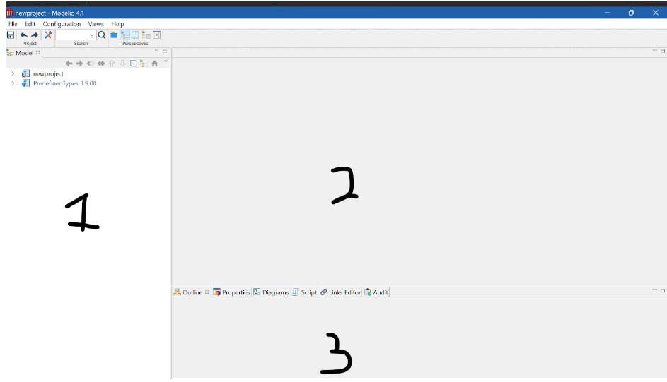
Understanding the User Interface
In the above interface, it is divided into three parts, the portion labelled “1” is the sidebar showing the project folder with components created from the class diagram, the work area is labelled “2” and the last part is labelled “3” which shows the different views your model can be displayed as.
We have a toolbar that consists of tools to use while working
Then lastly the menu bar, with options
Creating a Class Diagram with Modelio
Understanding Class Diagram Concepts
UML means Unified Modelling Language. It is a language used for modelling and specification development in software engineering. It makes use of class diagrams which is similar to Entity relationship diagrams to specify, visualize, document, and construct software systems. These class diagrams consist of elements that are used in this language.
Elements Used in Class Diagrams are:
Class - definition of a concept
Association - the relationship between concepts
Property- an object that defines a name, data type and cardinality
Package - a group of concepts
Enumeration - listed values to be changed for objects with the type “list”
Instance - when values change from one object to another. (It is rarely used)
Creating Class Diagrams in Modelio
Create a new project in Modelio to get started. When a new project is created, it generates files and directories for you to work with.
// The auto-generated project directory structure


|--- newproject

      |-- LocalModule

      |-- UML Directory

           |-- newproject     // this is an empty directory
Once this is done, you can take the following steps to create a class diagram.
Navigate to the empty directory under the auto-generated UML directory, then right-click and choose "Create diagram".
Select the type of diagram to be created and click “OK” to continue. The class diagram option is automatically selected.
Create your UML class diagram using the elements(class models) that have been generated in the work area.

When you want to select elements in the class model, you click on the item and drag it to the work area.
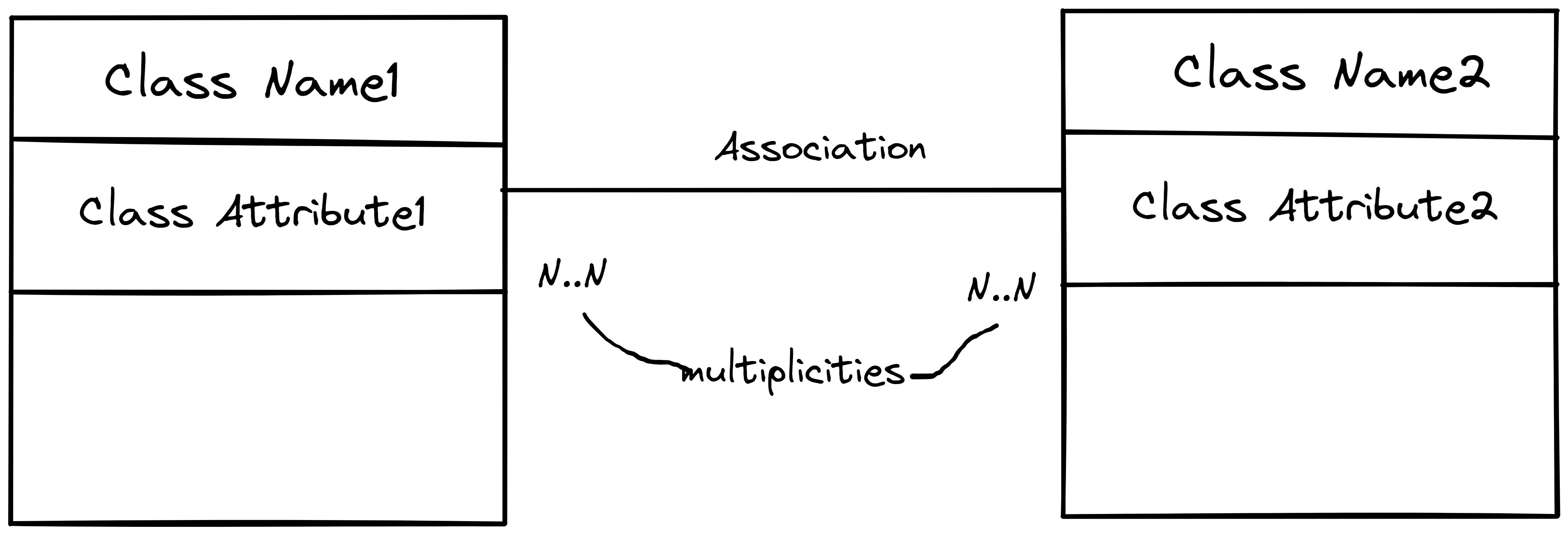
Defining relationships between elements and multiplicities
Class Diagrams are similar to Entity relationship diagrams. Entities can be represented as Classes and the relationship between other entities is represented as an association in the class diagram. The cardinality in ER diagrams represents multiplicities.
Entity Relationship Diagram

Class Diagram
Modelling an Example with a Class Diagram
System Description: In a burger ordering system, customers can choose any type of burger they want. Also, the burger comes with different types of cheese and meat, so customers can choose what they want.
Process
First, make a sketch of the description above to make modelling easier. That way we know the entities which are referred to as Class names in this notation.
Select the class notation in the class model and drag it to the work area.
Double-click notation to edit the class name in a new window with <Property> and <Value> tables.
Model the association between them. This association is denoted by a right arrow with a square. Hover over each element to see the name and definition.
Once the association is selected, click on one class notation to the other to connect them. By default, it shows an association/relationship name and multiplicities(cardinalities).
Double-click connecting line to edit the association name and multiplicities in a new window with <Property>, From: Customer and To: Burger table.
For the multiplicities, one customer can choose one burger, many customers can select many burgers. So set multiplicities as 1 to many customers and 1 to many burgers.
In the System description, it gives us more information on the Burger, saying it consists of different types of cheese and meat. These details are referred to as attributes or associations. An association is denoted by <a:> icon. To create an attribute, select the <a:> icon and click on the Burger class, that way an association is added. To edit the default name, double-click on the "attribute" name, and it brings out a new window, to change the name <Name>.
The resulting model provides a visual representation of the activity in a software system
Bringing all together
Summary
Modelio provides an intuitive and easy-to-use interface for creating visual models of software systems. By using class notations and associations, we can represent the entities and relationships within a system. With the ability to add attributes and edit multiplicities, Modelio allows us to create detailed and accurate representations of the system.